Spoiler Wing
A rear-wing concept assessed through CFD and FEA to check structural stiffness, pressure distribution, and local flow behavior.
- Role
- Mechanical design
- Year
- 2025
- Status
- Complete
- Context
- MNFG 310 - Advanced Manufacturing
- Rev
- A
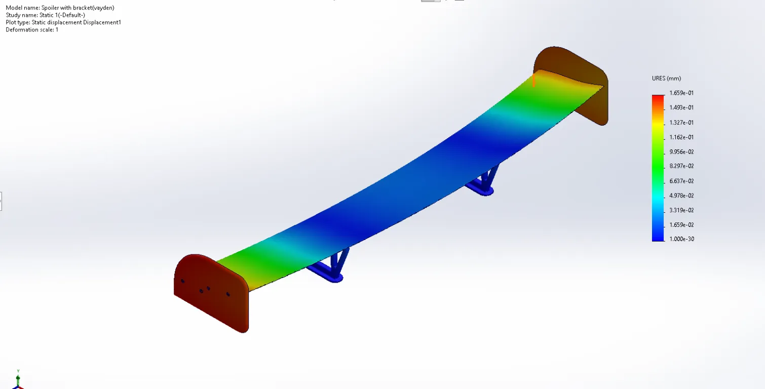
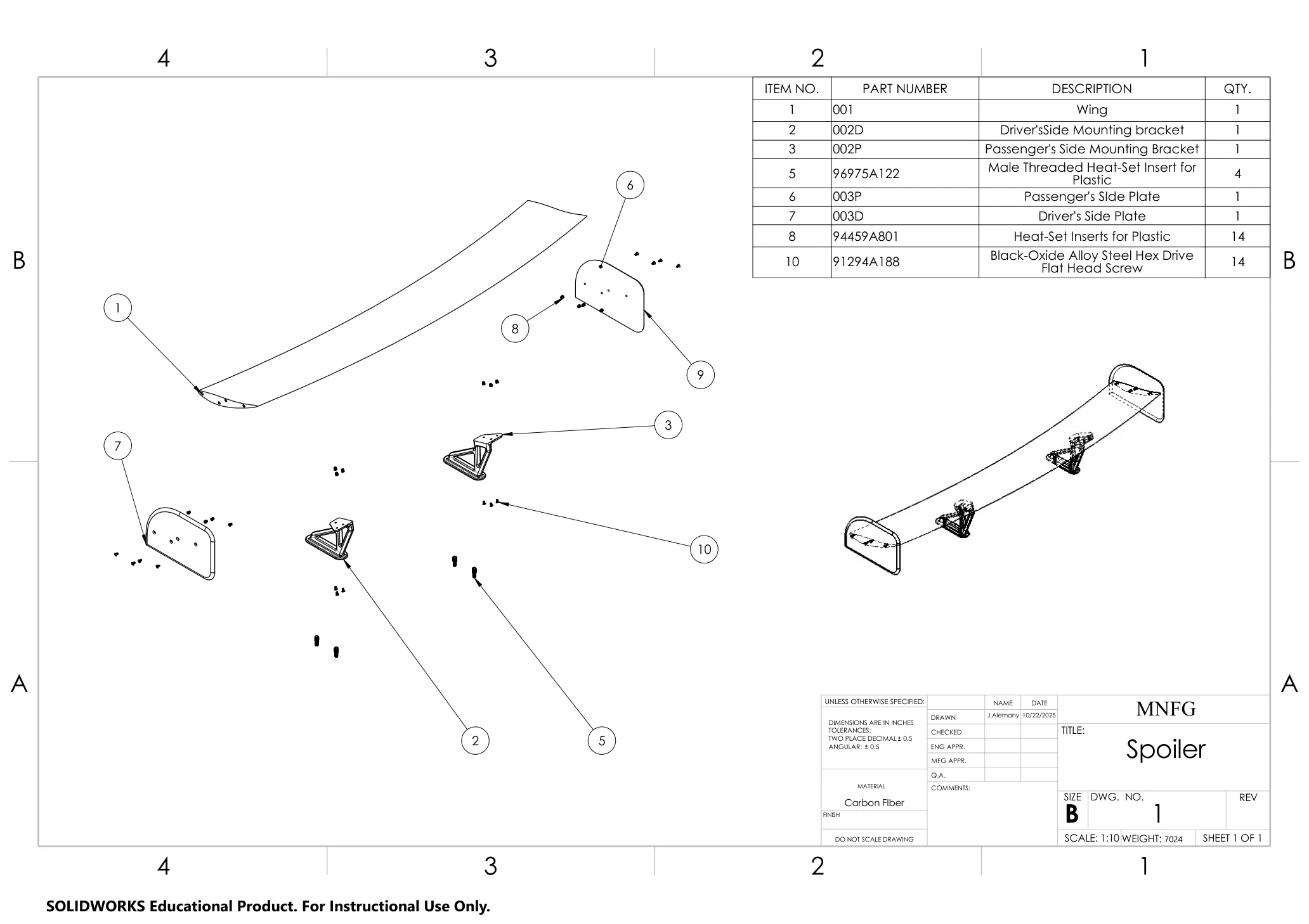
More views
Assembly layout and the main spoiler components from the design package.
Connection details and the hardware used to secure the assembly.
Aerodynamic and structural data used to validate the design concept.
Key numbers
- Max displacement
- 0.1659 mm
- Max static pressure
- 132,910 Pa
- Peak local flow velocity
- 240.21 m/s
Overview
This project examined a rear spoiler as both a functional aerodynamic device and a structural member. The design package included the main wing element, side plates, left/right mounting brackets, and the fastener system used to assemble the full rear wing concept.
The overall goal was to build a spoiler that could create a useful pressure differential while remaining stiff enough to resist bending and maintain a predictable load path through the mounts. The project was therefore not treated as a purely cosmetic add-on; it was evaluated as a lightweight, manufacturable aero component with real connection details and structural requirements.
Design approach
The spoiler profile was modeled as a swept, curved wing section with support points positioned to carry load into the mounting structure without introducing large local stresses. The design package shows the main wing, side plates, and the two mounting brackets as distinct components, which is a good reminder that the performance of the assembly depends on both the aerodynamic surface and the hardware that ties it together.
The assembly also used threaded inserts and drive-head fasteners to connect the main wing to the support structure. Those details matter because the wing’s stiffness and final alignment are directly affected by how the part is mounted and clamped into the assembly.
I then evaluated the concept using static structural analysis and a CFD flow study. This allowed the design to be checked for deflection, load transfer, and how the local pressure field behaved around the blade section and support geometry.
What I built
The project included a complete spoiler concept and a set of design drawings for the main assembly and the component parts. The major elements were:
- the main wing element
- left and right mounting brackets
- side plates for the spoiler body
- fasteners and threaded inserts for the final assembly
The drawings made the design intent clearer than a generic concept model because they show the geometry, part naming, and hardware relationship between the wing surface and its support structure.
Results
The static analysis showed a maximum displacement of 0.1659 mm, which indicates a stiff response for the loading case examined. The CFD results showed a maximum local static pressure of 132,910 Pa and a peak local flow velocity of 240.21 m/s. These values indicate the design produced a meaningful pressure field and maintained the intended geometry under the tested conditions.
From a design perspective, the project was successful as a proof-of-concept: the spoiler shape and support architecture were feasible, and the part package was detailed enough to make the manufacturing intent clear. The results suggest the assembly could generate downforce-relevant flow characteristics while keeping the structure well within a stiff displacement range for the tested loads.
What I would change
If the design were continued, I would focus on refining the wing section and bracket geometry to improve flow attachment and reduce turbulence generated near the mounting transition. I would also iterate on the hardware arrangement and material selection to move the concept closer to a realistic production and assembly process.