Bottle Line PLC Programming
A PLC control project for a simulated bottle-filling and packaging line.
- Role
- PLC programming
- Year
- 2026
- Status
- Complete
- Context
- ProSim bottle line simulation
- Rev
- A
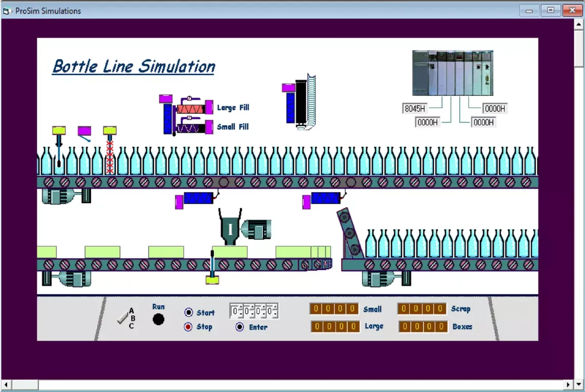
More views
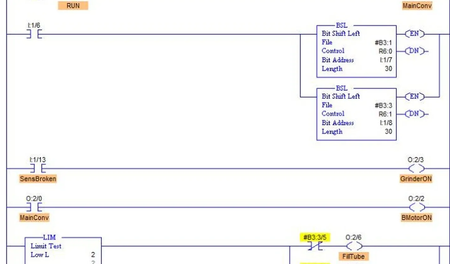
Full ladder-program printout. Open the image to zoom in and inspect individual rungs.
Project overview
This project uses the ProSim Bottle Line Simulation to develop PLC control for a bottle-filling and packaging process. The simulation screen shows conveyor sections, bottle-detection points, separate large- and small-fill stations, operator start and stop controls, and counters for small bottles, large bottles, scrap, and boxes.
The ladder-logic printout is included below, and the original .RSL assignment file is available to download. The program description below explains the intended timing, bottle tracking, scrap handling, and counter/display strategy. The .RSL file itself has not been modified.
I/O map
The table below transcribes the input and output assignments from the provided I/O map.
| Input device | Address | Output device | Address |
|---|---|---|---|
| Start pushbutton (NO) | I:1/1 |
Main conveyor | O:2/0 |
| Stop pushbutton (NC) | I:1/0 |
Scrap conveyor | O:2/1 |
| LS1 — Exist sensor | I:1/6 |
Divert conveyor | O:2/2 |
| LS2 — Size check sensor | I:1/7 |
Grinder | O:2/3 |
| LS3 — Broken check sensor | I:1/8 |
Scrap gate | O:2/4 |
| LS4 — Fill-tube sensor | I:1/9 |
Divert gate | O:2/5 |
| LS5 — Large sensor | I:1/10 |
Fill tube | O:2/6 |
| LS6 — Small sensor | I:1/11 |
Large fill | O:2/7 |
| LS7 — Cap-ram sensor | I:1/12 |
Small fill | O:2/8 |
| LS8 — Scrap-gate sensor | I:1/13 |
Cap ram | O:2/9 |
| LS9 — Divert-gate sensor | I:1/14 |
Run indicator | O:2/10 |
| LS10 — Scrap-box sensor | I:1/15 |
Small bottle count display | O:4 (mux O:2/11) |
| Large bottle count display | O:4 (mux O:2/12) |
||
| Scrap bottle count display | O:4 (mux O:2/13) |
||
| Box count display | O:4 (mux O:2/14) |
Address check: The I/O map names O:2/1 as Scrap Conveyor and O:2/5 as Divert Gate. In the ladder printout, those same addresses are labeled Box Conveyor and Small Bottle Door. Verify the intended output names and wiring against the running simulation before treating the two documents as reconciled.
Sequence and timing
The Start and Stop controls operate a latched Run state. When the line is running, the grinder and diverter conveyor are treated as continuous operations. The main conveyor advances bottles in timed steps: timer T4:0 provides the travel interval between stations, so filling and capping need to complete within the time before the next index.
At the entrance, bit-shift-left (BSL) instructions move detected bottle state through two 30-position tracking files. These stored bits represent the bottle’s progress through the process and let downstream rungs coordinate actions with its expected station position. Limit comparisons against the timer accumulator then create timed windows for the fill and classification logic. The rung comments and outputs show control for the fill tube, cap ram, large-fill and small-fill paths, and bottle-door outputs.
Scrap handling and box changes
The broken-bottle sensor starts the grinder output, while the tracked bottle state is used to time scrap handling farther along the line. The supplied operating notes call for the scrap gate to remain closed while the scrap conveyor is moving, and for the diverter conveyor to keep running. These are important sequence conditions to check during simulation testing.
The ladder includes a conveyor-related count that sets a BoxFull state at its preset and then operates the box conveyor. A separate sensor and counter detect box changes; the counter reset (RES) instructions clear the related counts as the next box enters the process.
Production displays
Individual counters track small bottles, large bottles, broken bottles, and boxes. TOD (to BCD) instructions convert the integer accumulator values to BCD for the simulator’s numeric display outputs.
Validation notes
- Download the original assignment file with the link below; it is provided unchanged.
- Confirm stop behavior, timed indexing, fill/cap windows, and scrap-gate interlocking in the simulator.
- Cross-check the written I/O map and operation notes against the ladder comments: the map labels
O:2/1as Scrap Conveyor andO:2/5as Divert Gate, while the ladder labels those outputs Box Conveyor and Small Bottle Door. - Resolve the counter description before treating it as final: the supplied narrative describes
C5:0as a broken-bottle count, but the ladder printout labelsC5:0asCONV COUNTER; the visible broken-bottle counter isC5:12. - Record observed results for start/stop, each fill size, broken-bottle routing, box-full, and box-change reset behavior.